 EN
EN
 中文简体
中文简体 English
LK Machinery
LK Machinery
LK Machinery
LK Machinery
LK Machinery
LK Machinery
LK Machinery
LK Machinery
LK Machinery

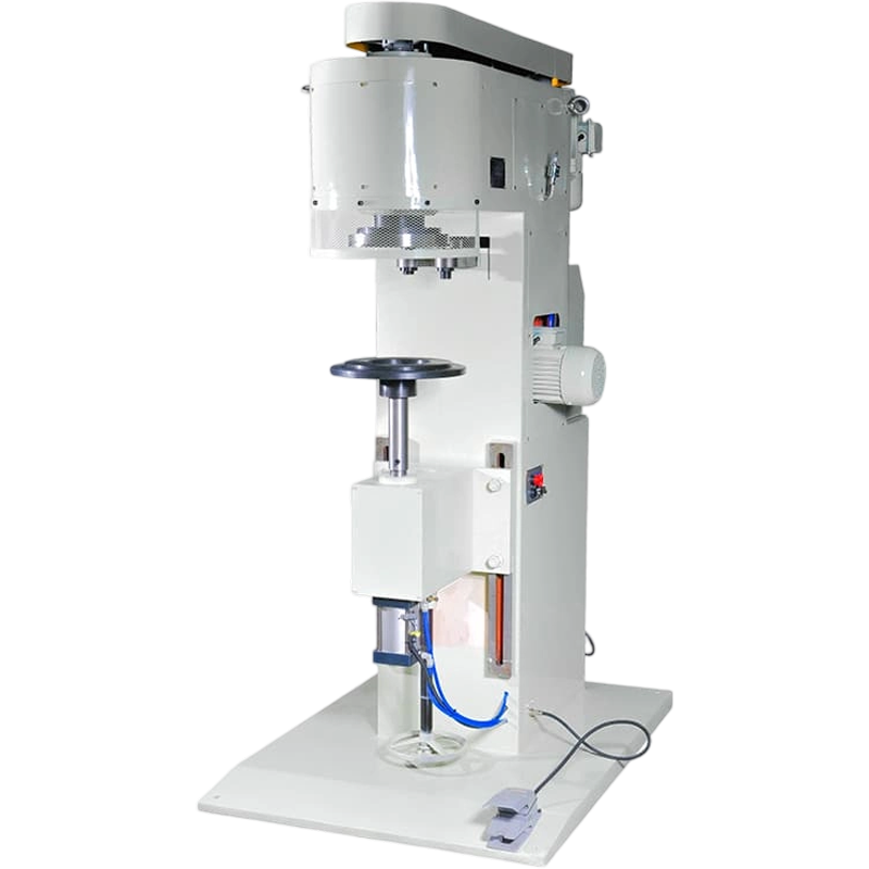
Use
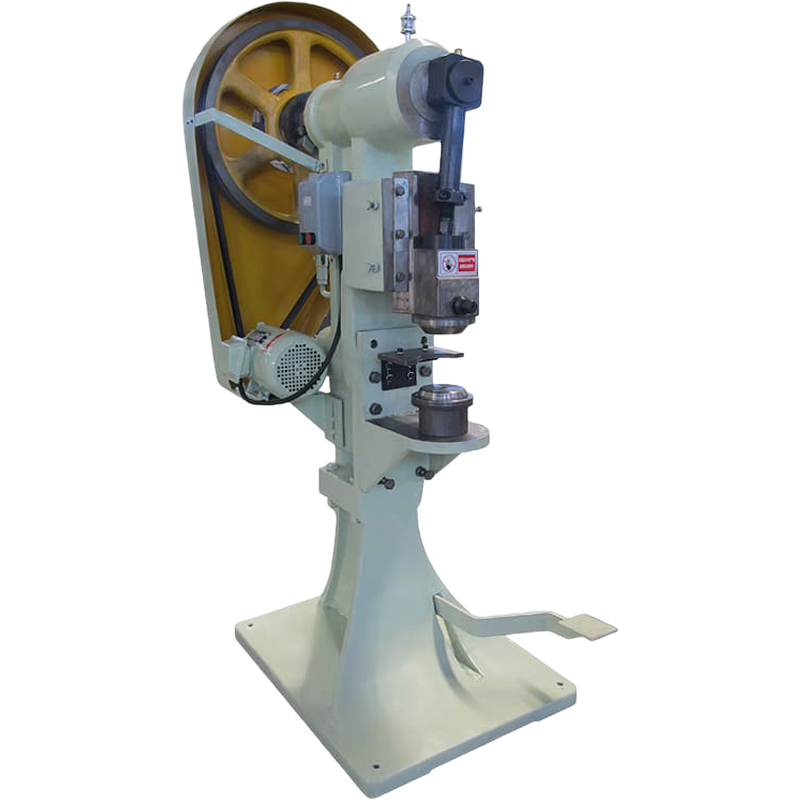
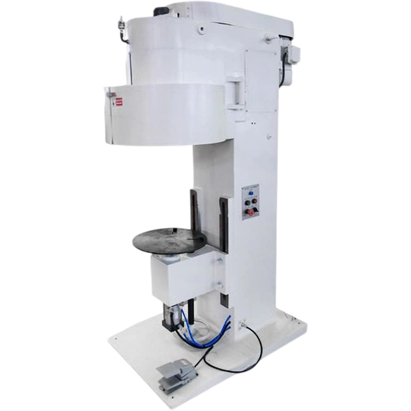
Suitable for sealing various round iron cans, glass cans, plastic paper cans, etc., this product is reliable in quality, easy to operate and lightweight, making it an indispensable and ideal equipment for the food and beverage industry.
Main technical parameters:
Production capacity: 10 - 15 pcs per minute
Application: Tank diameter 45 mm to 200 mm
Tank height 39 - 250 mm
Spindle speed: 620 rpm 520 rpm
Motor: jy7134 0.37 kW (vertical)
jy7134 0.37 kW (horizontal)
Size: 1350×700×450 (mm)
Total weight of equipment: 88 kg
(Note: For different tank diameters, corresponding upper pressure heads and partitions are required; two tanks with a height difference of less than 80 mm can share a single lifting rod, while if the height difference is greater than 80 mm, an additional lifting rod is required.)
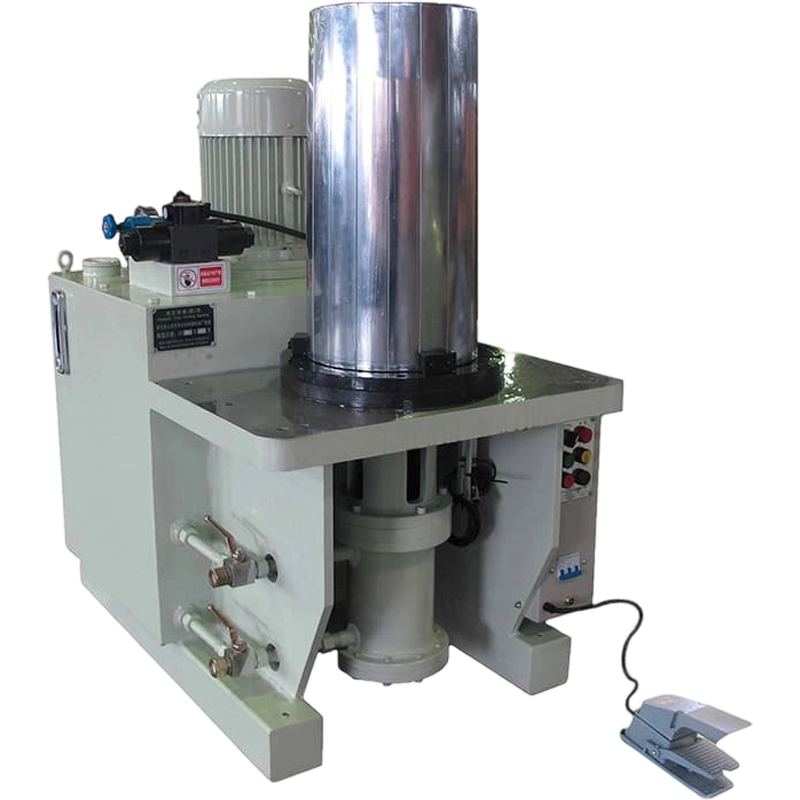
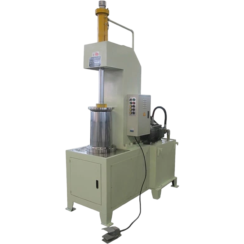
Working principle and operation method:
This machine consists of motor, pulley, main shaft, upper pressure head, column, lifting table, left and right rollers, camshaft and cam, gearbox, gear rack and other components.
The motor drives the main shaft and the upper pressure head to rotate through the V-belt, while the tank body also rotates synchronously. The upper pressure head also has the function of compressing the tank cap and sealing the tank body. The applied pressure is moderate and the left and right hobbing are on the camshaft. Under the action of the upper cam, the can lid is pressed from left to right, and the sealing process is completed.
Adjusting the tank diameter: Loosen the adjusting screw on the support plate to align the clamp arm bearing with the cam high point on the camshaft, adjust the pressure of the left and right rollers to press the tank cap, which can be fine-tuned by adjusting the eccentric shaft of the roller.
Adjust the water tank height: Loosen the adjusting screw under the lifting platform and tighten the nut after adjusting the height.
Use与维护注意事项:
1. Before use, press the left and right rollers tightly against the locking pad and clean the lift table.
2. Lubricate each rotating part.
3. Once an anomaly is detected, the machine should be stopped for inspection and troubleshooting.
4. Connect the ground wire!
Drawing instructions:
1. Belt cover 2. Axis 3. Upper motor 4. Support plate 5. Pressure roller arm 6. Hob
7. Small cam 8. Column 9. Lift adjustment screw 10, gearbox 11, large pulley 12, large gear 13, adjustment rod 14, upper pressure head 15, adjustment pad 16, camshaft 17, lift table 18. Adjusting nut 19. Lifting rod 20, helical gear 21, large cam 22, lower motor
Recommended Products


Leave a message online!
Contact Us
- Mobile: +86-13666712509
- Tel: +86- 0573-8802501
- Email: yuequ@lkmach.com
- Whatsapp: +86 136-6671-2509
- Address: No. 5, Huatian Road, Siqian Community, Cengang Street, Dinghai District, Zhoushan City, Zhejiang Province
Quick Links
Product
- Convenient barrel production line
- 18 L Square Tank Production Line
- 1-5 liter square tank production line
- 1-5 liter round can production line
- Tea cans, craft cans (square cans)
- 18.5 Conical coating barrel production line
- 18.5 Straight Paint Bucket Production Line
- Vacuum cleaner [housing] complete set of equipment
- 50 L Chemical Barrel Production Line
- Forming mold
- Can lid production line
- 18-20 liter barrel production line
Mobile
Copyright © 2025 Zhoushan Dinghai Lekai Can Machinery Factory
